


A few years back I entered a contest at 3DLuvr.com. This was (is?) a site that sponsored regular contests (with fabulous prizes!) for 3D artists, and when they announced this particular contest the prize was something I really wanted.
So I did enter, and in fact I won. The winner was required to write an article about his or her image – partly as a tutorial, and partly, I think, to prove its authorship – and I wrote tech article you’ll find below. Things seemed to be melting down at 3DLuvr just then, and in addition to never hearing from them after I was notified that I’d won, they never seemed to post the article. So here it is:
Making of – Warrior Tools
by Bradley W. Schenck
The idea for this contest entry came together out of a couple of different things I’d been doing lately. First off was the skull and crossbones design that you see here on the shield; I had just finished that Photoshop image recently as a T-shirt design, one of a series I did for a project at Saga Shirts. When I read the contest’s assignment I immediately wanted to use that design on a round shield. The second thing was a series of experiments I’d been doing this year with terrain, combining polygonal modeling with displacement mapping. It seemed natural enough to make use of that for the setting.
I worked on several ideas for the sword and shield before the picture really started to gel. Once I’d roughed in all of the basics I began to work pretty much from the ground up – literally – and that’s the way we’ll look at the evolution of the image.
1. The Natural Setting
Building believable, messy, natural looking environments in 3D has always been challenging. With every year our hardware has gotten faster, our available memory has increased, and we’ve gradually gotten much more to work with. Early this year I became interested in using displacement mapping for terrain and I happened across this very good tutorial by Peter Asberg. Because that tutorial is a great introduction to displacement mapping with a complex material I won’t try to duplicate it; I’ll just summarize it and point out some things I may have done differently.
There are a couple of ways to apply Displacement to an object in Max. What Displacement does is to disturb the normals of an object using a Max material as a guide. More resolution is added to the object at render time, leaving it faster in the viewports. Any Max-compatible map can be used for the Displacement map. White areas in the Displacement map are pushed out from the original position of the polygons. Where this differs from a bump map is that it actually changes the shape of the object; a bump map just renders bumps on the object’s original shape.
The idea is that because a displacement map is like any other map in 3DS Max you can build up a map using Mix maps, Blend maps, or any other Max maps to vary and customize the way that displacement works. In this picture my displacement map itself is really very simple, but the other parts of the material aren’t. So while the same displacement map is applied to everything, the diffuse maps, bump maps, and other parts of the material are masked over one another to create a combination of stone and sand.
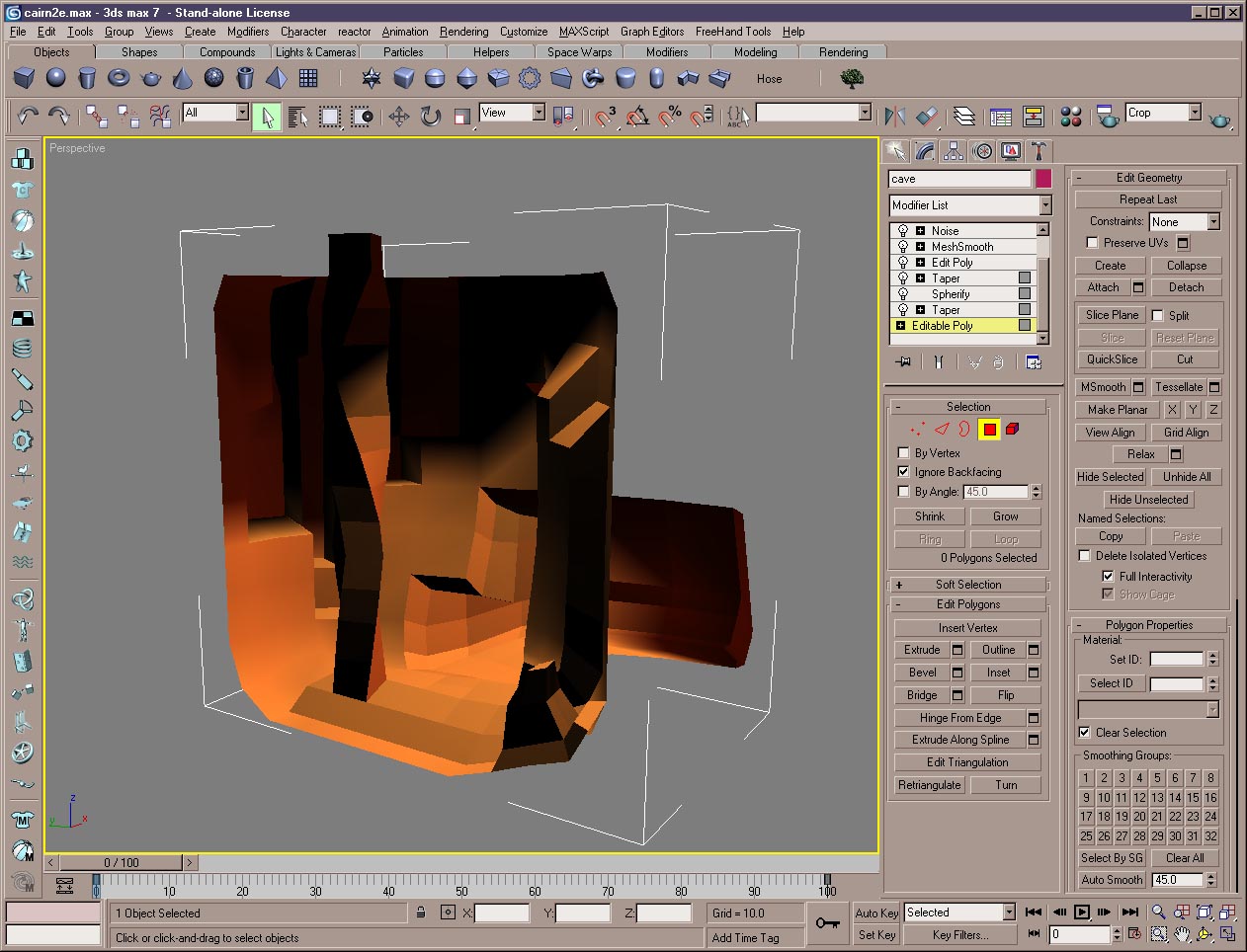 Figure 1
This is a shaded viewport image of the terrain as it was originally modeled. It’s a simple polygonal object with areas that have been extruded out or in – you can see, in the modifier stack, that I’ve later taken it beyond this stage.
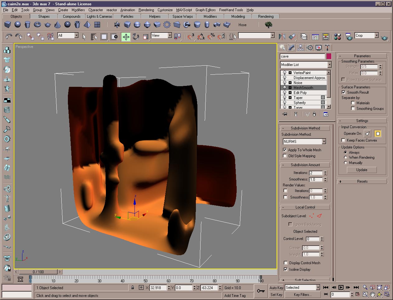 Figure 2
The terrain object is modified and Mesh Smoothed, resulting in its state in Figure 2.
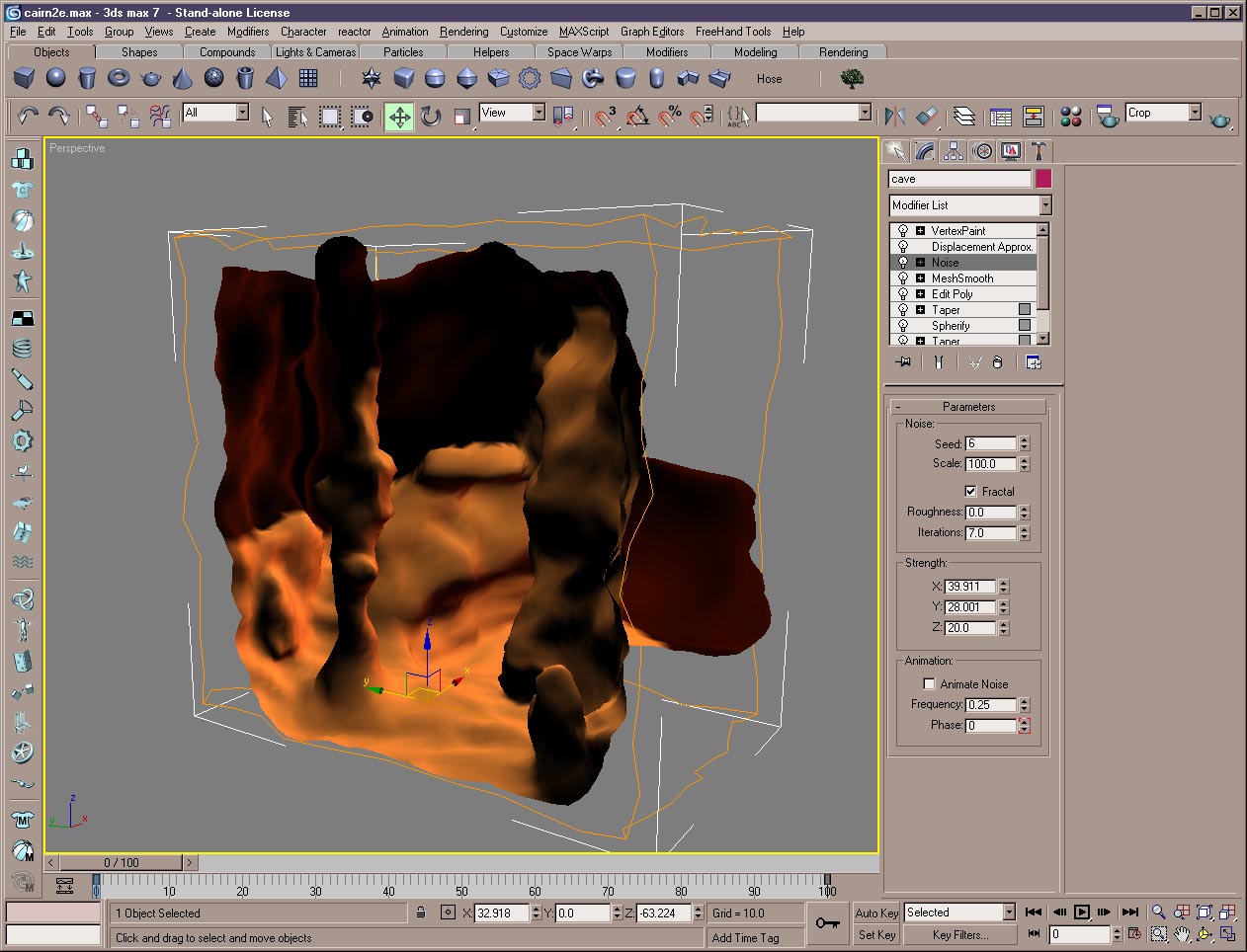 Figure 3
With the addition of a Noise modifier, we see what the final modeled version of the cliff face, ground and cave look like. All the further detail you see in the rendered image is achieved through its material, using both Displacement and Bump mapping.
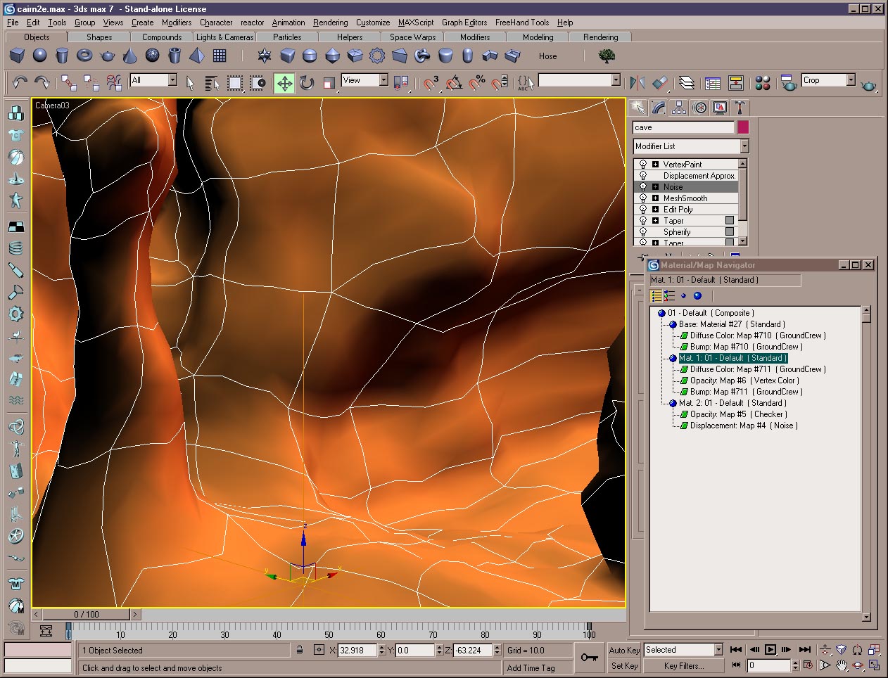 Figure 4
In Figure 4, we see the actual camera view used for the rendering with the terrain at this stage. At the lower right you can see the Material Tree for the Composite material I built up for the background. There are three submaterials in the Composite: the third one really only contains the Displacement Map. The reason for that is that while I’m working on a material I may swap the layers from position to position and it’s easier to keep track of where you are if the Displacement map is always in the last slot.
Max will only use one Displacement map in a material. That displacement map may include mix maps and blend maps, making it as complicated as a Composite material in its own right, but it’s only the last Displacement map in the material tree that’s actually used. I typically add the Displacement material as the last slot in the Composite material. You can see in Figure 4 that I have used an opacity map for that material – it’s a simple checker that is completely black. That makes everything about this material invisible, except the Displacement Map, which overrides opacity. So think of that last submaterial as an overlay that only performs Displacement on the object.
What remains are the two visible materials that create the stone and sand textures that blend together in the terrain.
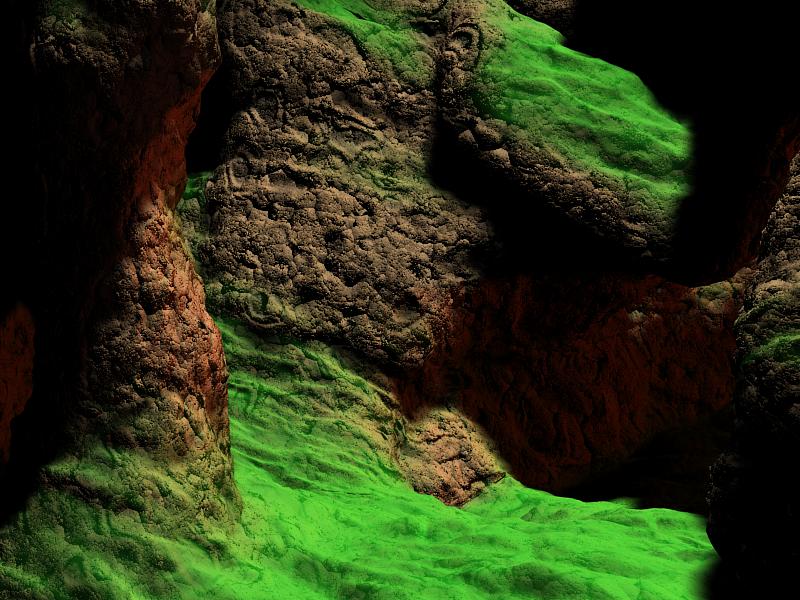 Figure 5
In Figure 5, I have replaced the sand material with a simple flat green. The displacement map is still being applied to the entire object, but it’s only the stone areas that are being rendered the way you see them in the final image. The stone and sand materials (or here, the stone and green) are being masked together using a Vertex Color channel in a tricky sort of way I developed to emulate a third-party procedural texture I used to use a lot in the days when I did my work with a ray tracer called Imagine.
That procedural texture was called “ABDust”, and it was a variation of a Noise texture which you could apply based either on World or Object space. If we picture it in World space, it would mix two colors together where one would be applied to the upward-facing horizontal surfaces of an object, while the other color would show on the vertical and downward-facing surfaces. The two would blend together in a turbulent noise pattern. The texture could be used as a mask between two different materials, which is how I usually used it.
I was able to use that texture in all sorts of ways and I’ve missed it since I started working with Max. I still don’t have a real re-creation of it, but for purposes of terrain – where you often want one dirt, sand, or other texture on flat ground, with another texture on vertical surfaces – I’ve worked out a sort of way to fake it.
I mentioned above that the two materials are mixed together using a vertex color channel. I didn’t start by painting that channel – I used a feature in Max’s Utility panel to create it.
If you go to the Utility panel and select “Assign Vertex Colors” from its list, you’ll find that you can bake lighting into the vertex colors. In order to create my mask I did just that: I set up a light directly above my terrain object, so that it would light the upward-facing horizontal surfaces, while the verticals would be left dark. Then I baked the lighting into the vertex colors of the object. A little Vertex Paint for touch-up, and I had a Vertex Color channel that I could use to mask my sand material onto the flat areas of the ground, leaving the stone material on the verticals. The two materials blend together at their edges and yield pretty good results, though not quite like that old procedural texture that I still miss so much.
The stone and sand materials themselves each use Digimation’s excellent “Ground Crew” plugin for their diffuse and bump channels. The Displacement map is simply a Noise texture; the stone really gets interesting when the natural-looking Ground Crew bump map adds a finer level of detail to the stony bits.
2. Other Background Details
The other features in the picture, apart from the “Warrior Tools” themselves, are the trees and the primitive altar. These are all polygonally modeled objects and there’s nothing very unusual in the way they were made.
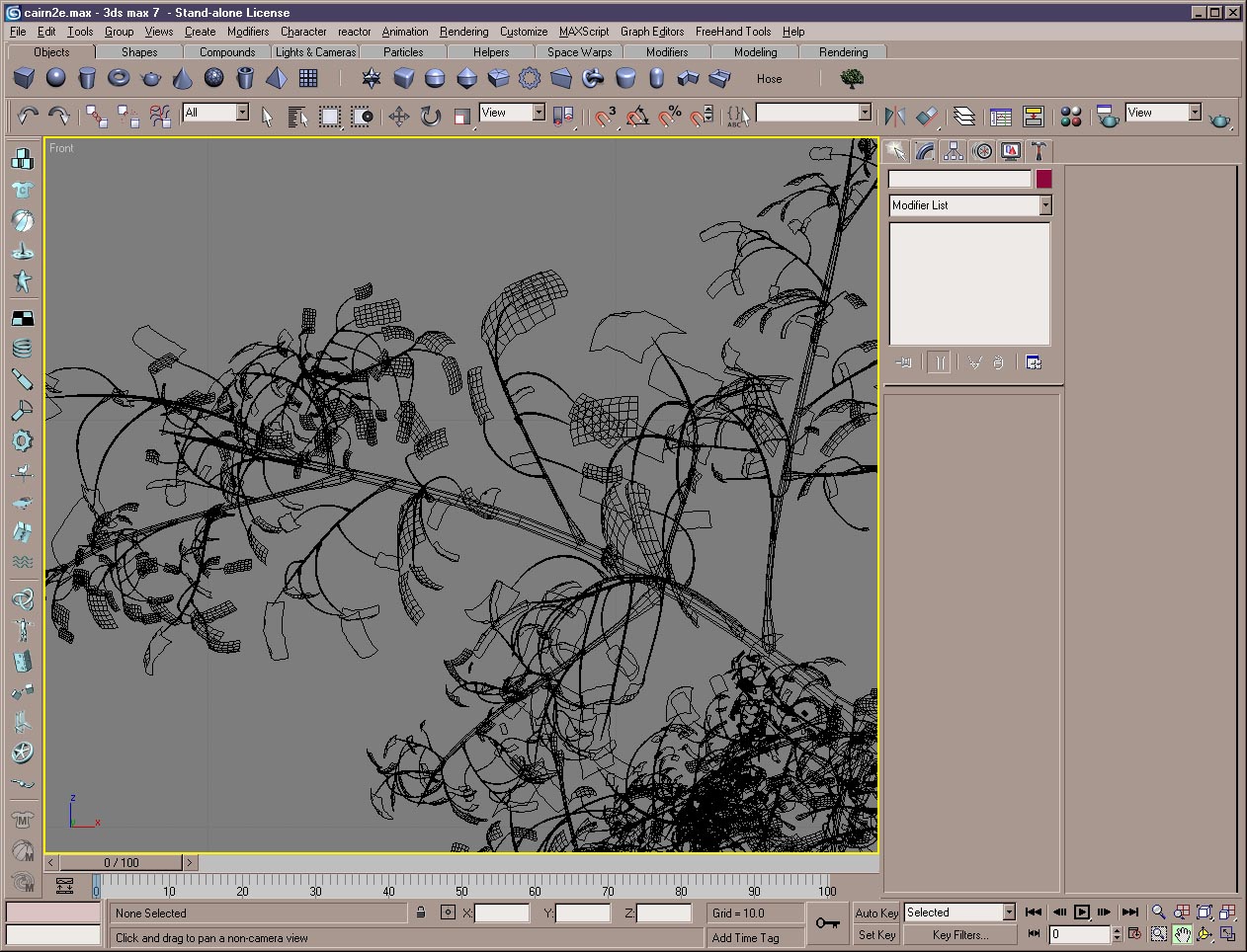 Figure 6
My trees were built using brute force, really. I built some basic branch and twig objects, did a lot of cloning, varied them (all right, I don’t remember this part. Probably I left Bend and Taper modifiers live on the cloned copies, varied their settings, and then attached them in groups). With a few branch groups built up, I repeated the process, scaling the groups up and down and positioning them together to create realistic branching patterns.
The leaves use a bitmap texture with an opacity map. You can see, in Figure 6, that there’s enough resolution in an individual leaf so that I could bend and twist them individually as I again cloned copies, scaled, rotated and positioned them in place.
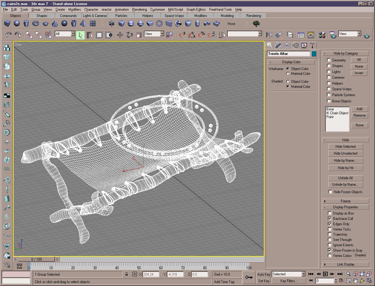 Figure 7
The trestle altar includes a wooden frame, built up from cylinders, a cloth “table”, built up from a box, the thongs that join them together, and an ornamented brass bowl. Because the bowl is only a single polygon thick its material was set to be two-sided. Its rim hides the edge and there was no reason to add additional polygons for its thickness.
3. The Sword and Shield
Well, this was what the contest assignment was all about. My original idea – to use my skull and crossbones design on a round shield – had led me in a piratical direction, which I’d continued by using beach sand for the ground, but I didn’t really intend for this to be a pirate picture. I was looking for more of an ancient or medieval setting.
I started out with leaf-shaped, early Iron Age sword designs but couldn’t work out something that seemed to click. So eventually I settled on more of a fourteenth century sword; a tapering broadsword with simple decorative hardware.
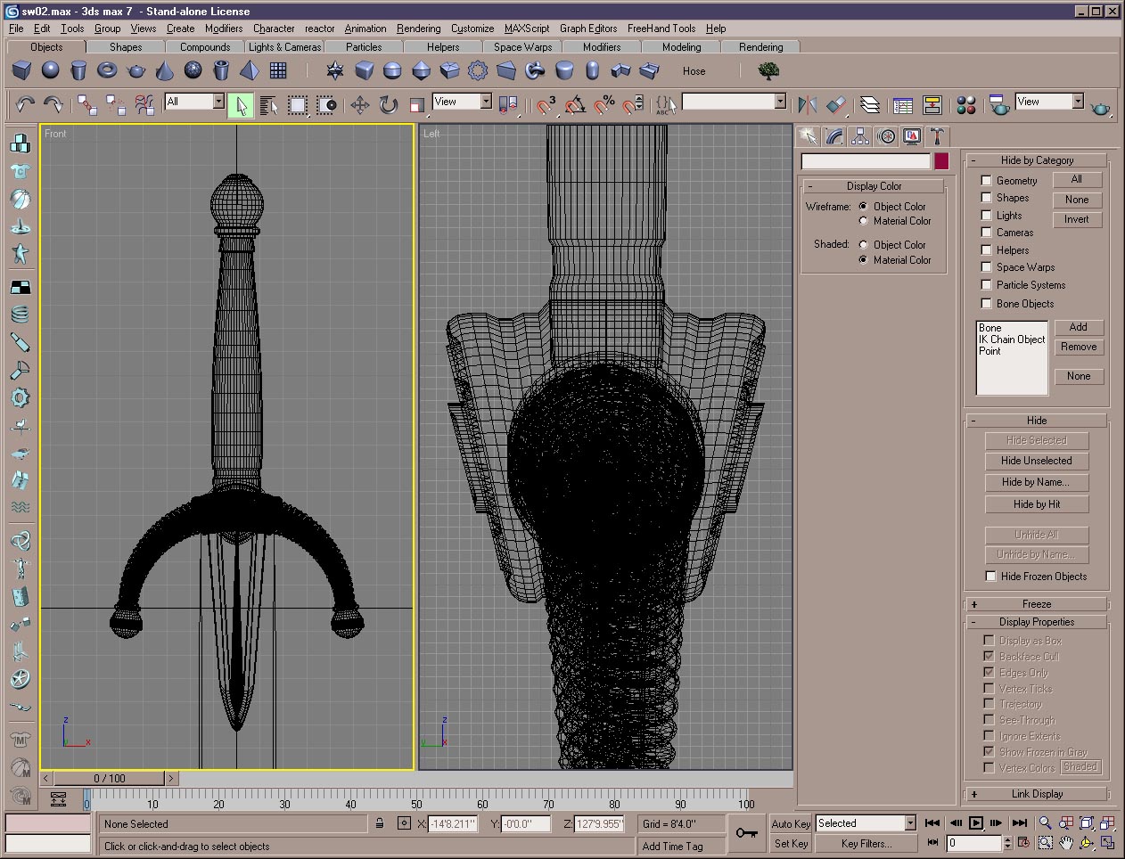 Figure 8
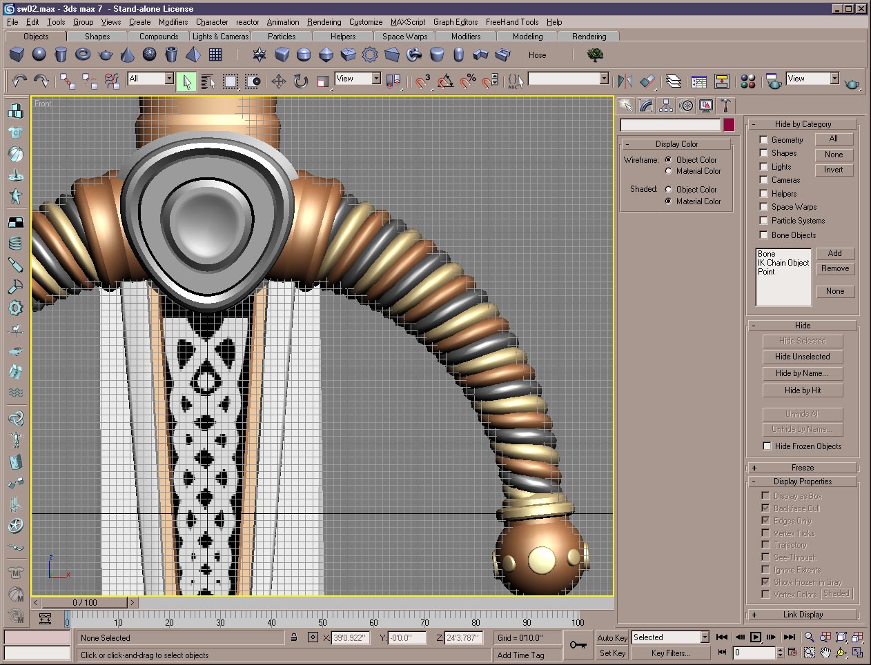 Figure 9
The quillons, or crosspiece of the hilt, are twisted cylinders; the central knob at the base of the blade is a seriously distorted Chamfer Cylinder, and so on. There’s a celtic knotwork design inlaid into the base of the blade and a textured wrapping on the hilt itself.
I worked out most of the materials in a scene with just the sword itself but metal surfaces are so dependent on their environment that I would be reworking them later in the main scene, with its final lighting.
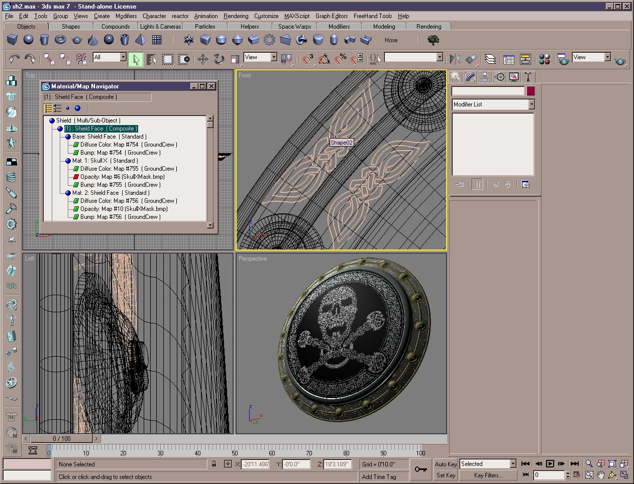 Figure 10
The face of the shield itself uses the skull and crossbones design, a complex Celtic knotwork pattern; more knotwork designs appear around the shield rim, but these are actually three dimensional. If memory serves, I painted them in Photoshop, converted them to vector images in Streamline, and then imported the vector versions into Max as splines.
Superimposed on the upper left viewport you can see the material tree for the shield face; it’s another Composite material. I’m using the skull and crossbones image as a mask for procedural maps – again, like in the terrain, I’m making heavy use of Ground Crew.
As time’s gone on I have been tending to use bitmap textures more and more as masks, rather than as painted textures. That’s certainly not always true; sometimes you simply need a painted texture in the scene. But it’s definitely a direction I’ve been headed.
This allows me to use an object at many levels of magnification, of course, and it relieves some of the problems you often find when mapping bitmap textures onto curved shapes. On the one hand, masks tend not to show distortion as much as painted diffuse maps (they’re overpowered by the textures they’re masking) and procedural maps really excel at texturing those types of objects because of the three dimensional nature of many procedurals.
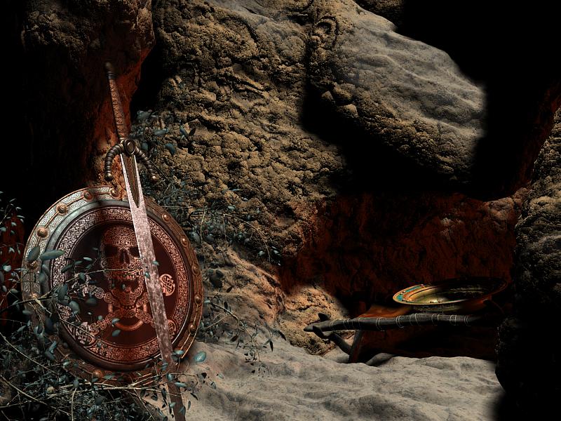 Figure 11
4. Rendering and Compositing
At this point, all the elements were in place, and so I finalized the lighting and rendered out the first version of the picture. I was planning to add particle smoke, but more about that in a moment.
Figure 11 shows the raw rendering. One unhappy accident of displacement mapping is that you can’t really tell where a displaced surface is going to end up when rendered; you can see near the top of the shield that the stone surface has displaced right through the rim of the shield. In an animation, I’d have probably had to correct that through trial and error. For a still image, though, I knew that I could simply render the scene without the terrain as a “Crop” rendering – which only renders a user-defined rectangle out of the whole scene – and then paste that over the glitch. So that’s what I did.
There were many adjustments I wanted to make, but all of them were going to be easier and quicker in Photoshop than in Max. The biggest missing bit here was still the smoke.
Here I was handicapped by the fact that I wanted to use Afterburn, which is a terrific particle rendering system, but since I didn’t have it I was working with its demo version. The demo version of Afterburn is not time limited, but while you’re using it, every time you save a file many (though not all) of the Afterburn settings get restored to their defaults.
This means two things: first off, you have to make sure that Max’s Autosave function is turned off. Otherwise you’re going to get awfully confused as the particle settings keep flipping back to their defaults. Second, and of course this is exactly why the demo is limited, you cannot save the work you’re doing. You can save the rendered images, of course, but after you close your Max file you’ll have lost anything you worked out with Afterburn.
For that reason I did the smoke in a completely separate file, which I never saved, and which I simply left open in Max for as long as it took to get some frames of smoke that I figured I could use.
I animated some smoke and rendered some of the nicer frames in Targa format, with alpha channels, so that I could paste them as transparent layers into my Photoshop version of the picture.
So that’s what I did. In addition, I made some changes to the rightness and contrast of the image, added some glows – though I often do these with a rendered specualrity pass, here I did it all in 2D – made some assorted touchups, and there we were at last, all done.
Well, nothing’s ever really done. I had so much interesting cliff face in the terrain that wasn’t visible in this picture that I started another, completely different picture where more of the terrain was visible. But that’s another story.
Warrior Tools Contest Rendering (Bradley W. Schenck)